
What are the benefits of improving power factor? (Part 1)
Electricity transmission and distribution systems are designed to carry a certain amount of current without overloading. Too much current causes excessive resistive losses in electric elements and can result in overheating and excessive voltage drop. If the reactive power of a load with poor power factor is not compensated locally, the reactive power needs to be supplied from the power source.
To maximize the capacity of the electric network, transfer of reactive power should be kept at the minimum. Utilities require certain level of DPF from power users and may penalize for excessive reactive power transfer from the power source. The increase in active power transmission capacity with the existing transmission and distribution system by local reactive power compensation is explained in figure 1.
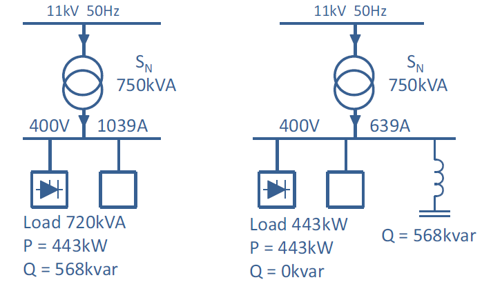
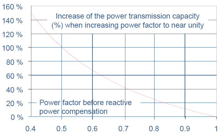
Since the nominal capacity of the transformer in figure 1 is 750 kVA, and no reactive power needs to be transmitted from the supplying network when local compensation is used, the whole capacity of the transformer can be used for active power supply. Thus, the increase in active power supply capacity in the case of figure 1 would be 750 kW – 443 kW = 307 kW. The increase in transmission capacity with respect to power factor improvement is presented graphically in figure 2.
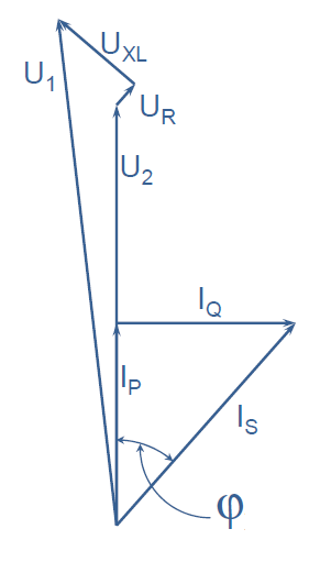
The load current floating through the transmission and distribution system causes power losses and voltage drop in the impedances of the network components. The phase to neutral voltage drop caused by active and reactive current is roughly

Where R is the resistance of the network and X is the reactance of the network. Since the ratio R/X is usually between 0.1 and 0.2, the voltage drop is mainly caused by the transmission of reactive current. Voltage support by reactive power compensation can be estimated with equation (6):

Where QC is the capacitor reactive power and SK is the short circuit level of the network at the point of compensation. In figure 8 is presented an example network supplying a 50 MW load with power factor of 0.75. This gives 44.1 MVAr of reactive load.
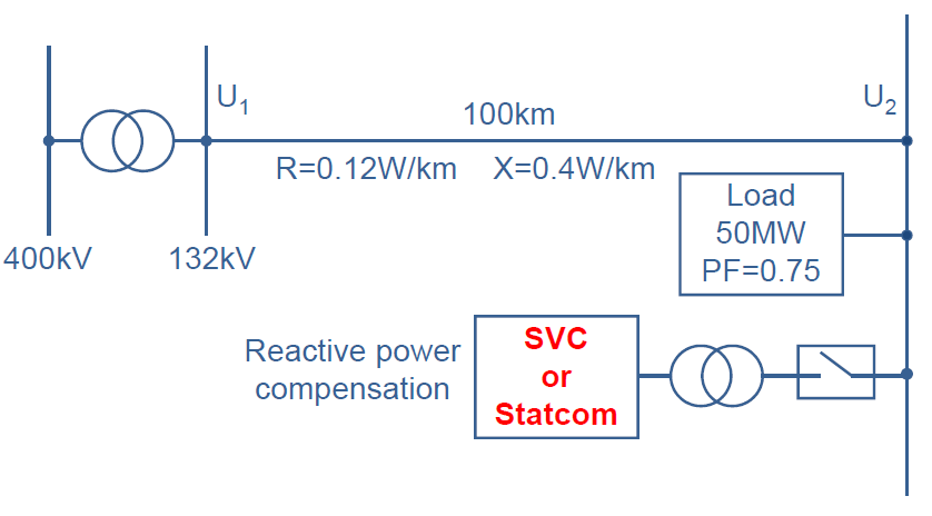
In figure 3 are presented the voltages U1 and U2 and the losses caused by the transmission of active and reactive power through the transmission line when the reactive power compensation equipment presented in figure 4 is not in use.
Anything on your mind? Let’s talk!

Riku Kalliomaa
Head of Sales, Power Quality Products
Global

Mikko Pohjola
Sales Manager, Active Harmonic Filter,
Key Accounts & OEMs

Viktoria Mansikkala
Sales Manager, Active Harmonic Filter
Partners, Europe

Pauli Halonen
Sales Manager, Active Harmonic Filter
Finland

Juhani Jaatinen
Senior Sales Manager,
DACH, Benelux, France, APAC

Venkatesh Ramachandra
Regional Sales Manager,
Middle East