
Basics of reactive power compensation (Part 2)
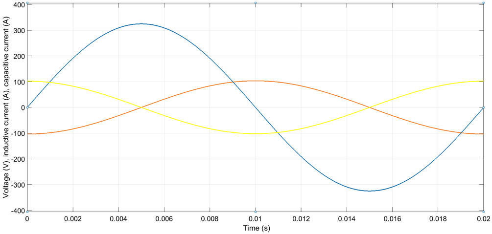
Inductive elements, such as transformers and magnetizing coils in AC motors, store energy into their magnetic field. The direction of the magnetic field (is such that it) opposes the change in voltage. Thus, when supply voltage increases, the net voltage over the inductive element increases more slowly due to the opposite voltage induced by the inductive element. Since current is proportional to voltage, also the current in the circuit lags the supply voltage. In a purely inductive circuit the current lags the AC voltage by 90 degrees.
Capacitive elements, such as capacitors, cables and overhead lines, store energy into their electric field. When the charge of a capacitive element is zero, the electric field and voltage over the element are also zero. Thus, when voltage is applied over the capacitive element, the element momentarily represents a short circuit and the current is at the maximum. When charge builds up, the voltage generated by the electric field increases and the net voltage in the circuit decreases. Hence the current decreases too. In a purely capacitive circuit the current leads the voltage by 90 degrees.
Figure 1 shows the currents in a purely inductive circuit and in a purely capacitive circuit. Figure 2 shows the respective powers.
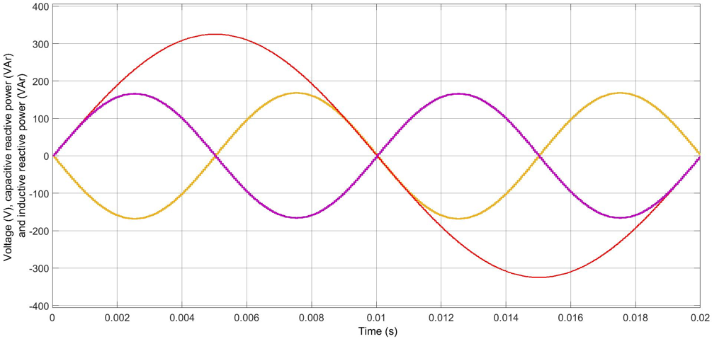
From Figure 2 it can be seen that unlike in a resistive circuit, in a capacitive or inductive circuit the instantaneous power oscillates between negative and positive maximum, averaging to zero over one network cycle. The power returning to the source in each cycle is called imaginary power or reactive power. No net energy can be transferred with reactive power.
In practical networks there are both resistive and reactive loads. The total power is a vector sum of active power and reactive power and is known as apparent power. Figure 3 shows the three powers in vector format.
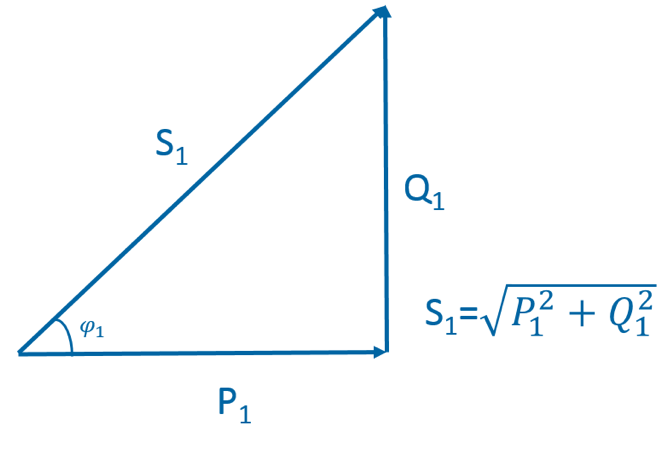
The portion of active power P of the fundamental frequency apparent power S1 is called power factor or more properly displacement power factor (DPF). DPF is calculated as
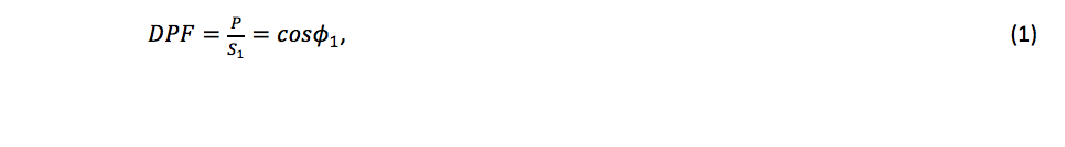
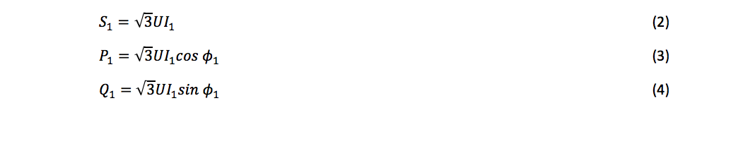
where ϕ1 is the phase angle between the fundamental frequency voltage and current. The word ‘displacement’ in DPF indicates the displacement between the voltage and current phase angles in a reactive load. In a 3-phase system apparent power, active power and reactive power are calculated with formulas (2)-(4), respectively.
Do you have any questions?
Please contact one of our salespeople with questions and inquiries.


Lasse Hietikko
Sales Manager, Power Quality,
Hydrogen & Renewables

Juhani Jaatinen
Senior Sales Manager,
DACH, Benelux, France, APAC

Venkatesh Ramachandra
Regional Sales Manager,
Middle East