What is harmonic resonance, and how can it damage electrical systems?
Harmonic resonance occurs when the inductive and capacitive elements of an electrical system create unusually high or low impedance at a particular harmonic frequency. If a Variable Frequency Drive (VFD) or another non-linear load injects harmonic current near that frequency, the harmonic voltage or current can be strongly amplified, causing equipment overheating, protection trips, and even component failure.
Harmonic resonance is a phenomenon caused by the interaction of independent electrical components in an electrical system. The potential for harmonic resonance is inherent in electrical systems, but the phenomenon is becoming increasingly relevant as nonlinear loads and power-electronic equipment become more prevalent.
A given electrical system has natural resonant frequencies, i.e. frequencies where there is a peak in network impedance from a specific point of observation. These resonant impedance peaks are formed by the interaction of inductive and capacitive components at given frequencies. Useful way to think about this is to understand that harmonic resonance risk is always present, but a resonant frequency itself does not necessarily cause a problem. Problems arise when a harmonic source excites the network at or near that frequency.
Every electrical network has inductive and capacitive components, some examples listed in the table below. In addition to this, every electrical system contains more complex stray capacitances and inductances.
| Typical capacitive components in electrical networks | Typical inductive components in electrical networks |
|---|---|
| Cables Overhead lines with light loading Shunt and series capacitor banks Surge capacitors EMC filters and LCL filters | Transformers Overhead lines with loading Direct-on-line electric motors and generators Chokes and reactors |
What determines the resonant frequency?
The impedance of the network can be factored into capacitive and inductive reactances. Inductive reactance always increases with frequency whereas capacitive impedance always decreases with frequency. For given inductance L and capacitance C (from a given point of observation), the resonant frequency can be found by
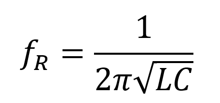
, which is the point where the inductive and capacitive reactances intersect. The resonant frequency is typically not static as the overall inductance and capacitance change with changing loads and upstream network status.
Parallel and series resonance
The harmonic resonance phenomenon can be further broken down to series resonance and parallel resonance, but the parallel resonance is typically the more interesting in condition distribution network – or plant internal network – level, i.e. where Variable Frequency Drives (VFDs) and other typical harmonic sources are installed.
In parallel resonance, the network impedance becomes very high – the impedance ZH is peaking on a resonant frequency. If a harmonic current IH is injected, according to Ohm’s Law
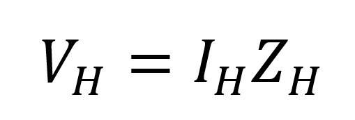
the harmonic voltage at that frequency also rises, producing voltage distortion. The harmonic current may itself be relatively modest, but in a resonant condition, it produces extraordinarily high voltage distortion.
Series resonance is essentially the opposite. At the harmonic frequency fR, the impedance becomes so low that the harmonic current on said frequency can be strongly amplified and exceed beyond planned current capacities.
How does series resonance affect capacitor banks?
In practice this matters most of the capacitor banks, when observed from the upstream network. The same transformer-and-capacitor series combination that forms a parallel resonance from the VFD’s viewpoint forms a series resonance from the grid’s viewpoint. Background voltage distortion can already be present in the supplying network that then drives amplified current into the capacitor bank. A plant with no significant harmonic source of its own can therefore still suffer repeated capacitor fuse operations, driven entirely by distortion originating outside the facility.
Parallel resonance example with capacitor banks
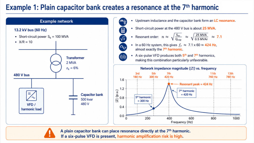
Adding a capacitor bank (traditionally used for power factor correction) to an electrical system where there is a harmonic source – VFD in this example – illustrates the resonance condition very well. In below Example 1, the feeding transformer and capacitor bank create a parallel resonance circuit from the VFD point of view (and a series resonance circuit from the upstream network point of view). The resonant frequency is exactly in the range where characteristic harmonics from a six-pulse VFD typically appear. With capacitor banks, the resonant frequency (or harmonic order) can be roughly estimated by
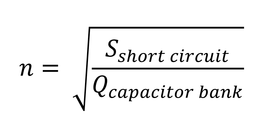
This problem has been traditionally solved by adding a detuning reactor to the capacitor bank, which shifts the resonant frequency lower (below the characteristic harmonics of a VFD) and thus reshapes the impedance frequency response, as illustrated in Example 2.
The evolution of capacitor banks for power factor correction has been discussed more in our other article.
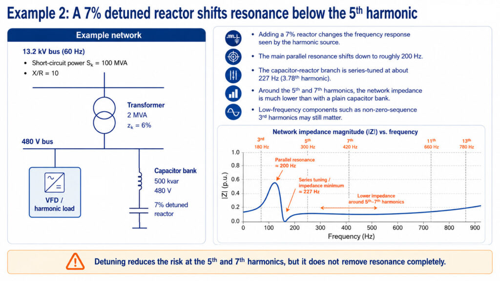
Detuning the capacitor bank therefore shifts the resonant frequency, but it still exists.
How does grid strength affect harmonic resonance?
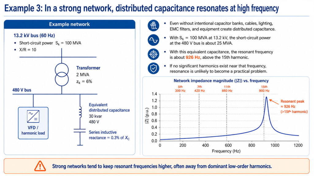
Examples 3 & 4 show the significance of upstream network strength. As a rule of thumb, the weaker the upstream network is, the lower the resonant frequency appears. This is significant since, typically, the prevalent harmonic currents from typical harmonic sources are at lower frequencies, and therefore problems are more likely to appear.
In Examples 3 and 4, the distributed capacitance is expressed as an equivalent 30 kVAR shunt capacitance at 480 V. The reactive power such a capacitance would draw at fundamental frequency represents the combined effect of cables, EMC and LCL filters, lighting ballasts, and surge capacitors. The 0.3% series inductive reactance represents the cable and filter inductance in series with that capacitance.
Example 4 shows how the resonant frequency shifts significantly, when the network strength is 10 times lower. It is important to understand that whereas changes this big in the fault level are not typical, unless the network starts operating in an island (for example when a facility or areal network network is powered with diesel generators after mains failure). In such situation the risk for harmonic resonance is significant. Regardless, the network strength is never static, and it changes all the time due to load and production changes, meaning:
- Network topological changes
- Upstream generation (rotating machines connected) and infeed
- Islanding
- Loads connected or disconnected locally (for example more VFDs with more LCL filters connected to the grid)
Why do changing network conditions matter?
‘Source impedance changes with network topology, upstream generation and islanding, while the local capacitance, inductance and damping change as cables, capacitor stages, filters, converters and loads are connected or disconnected. This can make the harmonic resonance condition elusive, and it sometimes appears and sometimes disappears.
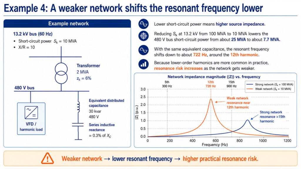
It is worthwhile to note that a tenfold reduction of the fault level shifts the resonance frequency considerably less than by a factor of ten. This is because the series inductance in the capacitive current path is a major part of the source inductance that the capacitor sees. The weaker the network becomes relative to that branch, the more directly the resonant frequency tracks the source impedance.
Why damping matters as much as frequency
Resonant frequency determines where the impedance peak sits. Damping determines how high it rises. All components in an electrical network have also a resistive component, albeit small due to the fact normal equipment is not perfectly conductive. These natural “parasitic” resistances in the network, such as cable and transformer resistance, and potentially resistive loads by their nature dissipate the oscillating energy and limits the peak. A resonance at the 7th harmonic in a heavily loaded plant may never cause a problem; the same network at 20% load can produce voltage distortion several times higher at the same frequency.
This explains one of the most common real-world patterns: problems appear at night, at weekends or during shutdowns, when process load is off, but a capacitor bank or another capacitive element such as a long underground cable remains connected. Load shedding removes damping and, because for example direct-on-line motors also contribute inductance, it can shift the resonant frequency upward at the same time.
How do I identify harmonic resonance?
Harmonic resonance can often be seen as levels of Current Total Harmonic Distortion (THDi) or Voltage Total Harmonic Distortion (THDu) that cannot be explained by the level of harmonics injected to the network by the harmonic sources. High currents may be present in some switching situations. The surest way to identify it would be to conduct a power quality survey in the facility, meaning measurements over a reasonable period of time (or as mandated in power quality measurement standards) that show different load connection situations. In detail, one of the following conditions may imply harmonic resonance:
- one individual voltage harmonic is disproportionately high
- THDu changes sharply when loads change or capacitor stages switch
- capacitor RMS current is unexpectedly high
- a harmonic problem appears only under certain grid configurations;
- unexplained capacitor fuse operations or protection trips occur
- harmonic levels change dramatically between grid-connected and generator/island operation
If there is already damage or these problems have been identified to appear for example when capacitor banks or other capacitive loads are connected, carrying out the measurements when the loads are not connected and subsequently when they are connected should bring clarity on how power quality metrics develop between the two loading conditions.
In addition to measurements, frequency scans and harmonic impedance studies can help confirm the source of the resonance, if the network topology and operating scenarios are known.
Practical effects of harmonic resonance
High voltage distortion and/or uncontrollable harmonic current potentially cause a variety of issues that often lead to relay tripping – and interrupted production – or even equipment damage and failure.
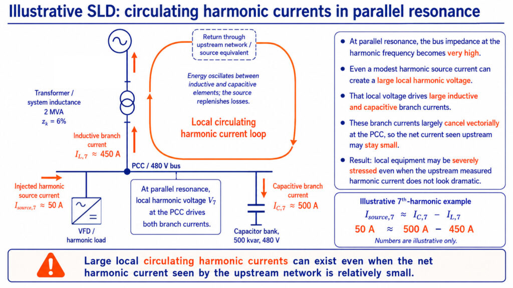
Although we discussed above that parallel resonance primarily increases the voltage distortion, it can also create circulating harmonic currents in the resonant frequency (that circulate in the same bus under the transformer) that is much higher than what can be observed in the upstream network, as they largely cancel each other vectorially ( leaving only the injected source current) in the Point of Common Coupling (PCC) upstream the feeding transformer, but that can be so high that they cause relay tripping and/or equipment failure.
Why do circulating harmonic currents occur?
The circulating currents are, in fact, the consequence of the high voltage distortion, as the voltage distortion itself creates high inductive and capacitive current components that are oscillating between the local network’s inductive and capacitive components, i.e., between the inductors’ magnetic fields and capacitors’ electric fields. Oscillation would be naturally damping in the parasitic resistances of the network, but the harmonic source, such as a VFD, is the provoking force injecting just enough harmonic current to keep the oscillation going. More specifically, the VFD needs to inject only enough harmonic current each oscillation cycle to replenish the energy lost in the resistances of the local grid – this is called natural damping – to keep the oscillation going. When resonance occurs, you could conceptually have Icapacitive=500A and Iinductive=450A (both of which cancel each other at the PCC), but at the harmonic source only Iharmonic source=50A. The circulating currents phenomenon is illustrated in the figure below.
How does harmonic resonance damage electrical equipment?
Both phenomena can cause a lot of potential problems in the electrical network, as exemplified by the table below.
| Point of failure | Failure mechanism |
|---|---|
| General equipment tripping and failures | Protective limits are reached and equipment shuts down, circuit breakers open or internal fusing blows as self-protection measure. |
| Thermal overloading of transformers | Harmonic currents increase RMS copper losses and frequency-dependent winding eddy-current losses, producing winding hot spots and accelerating insulation ageing. |
| Capacitor bank or filter capacitor | Harmonic voltages produce high capacitive currents in RMS that cause dielectric and conductor heating and fuse or pressure-disconnector operation and accelerated insulation ageing. |
| Motor | Distorted voltage causes harmonic stator and rotor currents which in turn produce positive and negative sequence magnetic fields. They cause excess heat losses and pulsating rotor torques that can be observed as mechanical vibration. |
| Cables and busbars | Increased thermal losses due to higher harmonic RMS current. AC resistance increases at higher frequencies due to skin and proximity effects. This can cause increased conductor temperature and accelerated conductor insulation aging. Severe overheating can ultimately damage the insulation. |
| Reactors and chokes | High harmonic RMS current causes excess copper and core losses that cause winding temperature to rise and insulation ageing. |
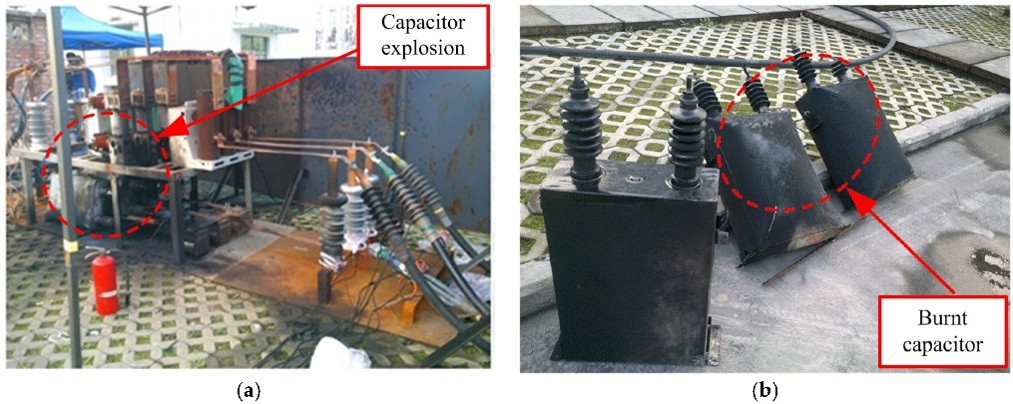
An example of what severe overvoltage can ultimately cause to network equipment can be seen below:
Mitigating the risks of harmonic resonance
Although with the principles discussed above, one may have a general idea of potential harmonic resonance frequency ranges, due to changing load conditions and changing feeding network conditions, in practice the resonant frequencies change all the time. This makes the phenomenon hard to predict. Frequency scans and harmonic impedance studies can predict resonance conditions fairly well when the network model and operating state are known, but it is complex to model every scenario during the lifecycle.
Taking power quality into account from the very beginning in electrical grid design processes helps avoid resonant conditions, but as the phenomenon is difficult to predict, it may appear in certain network conditions anyway.
There are various ways to mitigate the risk of harmonic resonance:
- Building unproportionally strong networks, but this is not economically or practically sensible.
- Moving the resonant frequency peak by detuned capacitors (adding various detuned or filter capacitor banks can however create also new resonant frequencies)
- Reducing the harmonic current at the source by line reactors / AC chokes or DC chokes
However, none of the above are actually actually able to dampen the resonant peak itself; they are rather ways of going around the problem.
How does resonance damping work?
Merus® A2 Active Harmonic Filter has a Resonance Damping feature that actively reduces the network impedance peak around a resonant frequency. Unlike detuning, which primarily moves resonance away from problematic harmonic frequencies, active damping targets the magnitude of the resonant response itself by behaving as a conductance at harmonic frequencies. As the response can be tuned by parametrization without changing equipment, this also works in changing network situations. This resonance damping feature can be taken into use already in the design process of an electrical network, or the filter may be installed later if such a condition appears. Because active damping can operate across a frequency range, it can remain effective even when changes in network configuration shift the resonant frequency. More on this feature in our other blog post.
Anything on your mind? Let’s talk!