
Harmonic resonance in VFD installations: How resonance damping reduces voltage distortion
Variable Frequency Drives (VFDs) are widely used to improve motor control and reduce energy consumption. However, as more VFDs are connected to the same electrical installation, the power system becomes increasingly sensitive to harmonic resonance.
The problem is not only that VFDs produce harmonic currents. The more difficult issue is that the electrical network itself can amplify some harmonic frequencies. When this happens, a harmonic current that would normally be acceptable creates a high harmonic voltage distortion at the switchboard or Point of Common Coupling (PCC). This is why resonance damping is important in modern VFD installations.
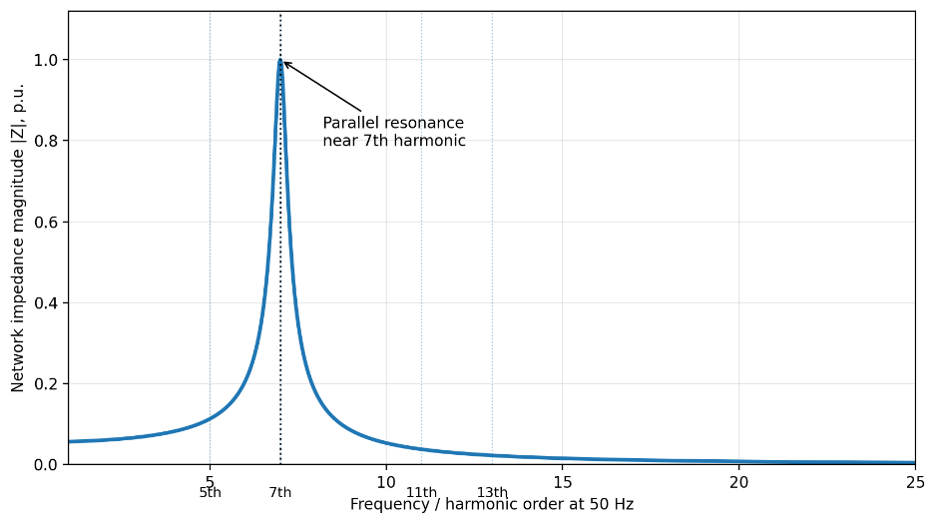
For harmonic power quality, the critical case is usually a high-impedance resonance seen at the consumer or PCC. The Variable Frequency Drive is a harmonic current source, whereas the distribution network is the transfer path. Even a moderate harmonic current can create excessive harmonic voltage when the network impedance has a narrow peak at the same frequency.
What causes harmonic resonance in VFD installations?
Harmonics are often discussed in connection with mains voltage quality in installations using VFDs. In this blog post, the focus is not on the harmonic currents generated by the VFDs themselves, but on harmonic resonance in the electrical network.
In most installations, individual harmonic voltages in the mains supply are relatively low. However, if the network has a parallel resonance near one of these harmonic frequencies, even a small harmonic component can be amplified to a level that causes operational problems. The effect can appear as excessive voltage distortion, circulating harmonic currents, nuisance tripping, malfunction of connected equipment, or, in severe cases, equipment damage.
The resonance frequency of a VFD installation is not necessarily fixed. It can change when the network loading changes, when VFDs are started or stopped, or when motor and other dynamic loads alter the effective system impedance. Although these loads can shift the resonance point, VFDs and motor loads generally do not add enough damping to suppress the resonance peak.
Therefore, a system may operate normally under one loading condition but exhibit high harmonic distortion under another. The same installation may amplify the 7th harmonic in one load condition and the 11th or 13th harmonic in another.

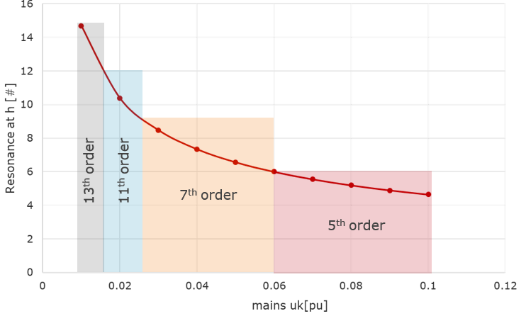
Harmonic resonance in VFD installations is not limited to high-order harmonics. Under certain combinations of upstream grid impedance, transformer impedance, cable capacitance, and VFD input/DC-link capacitance, the network natural frequency can drop into the characteristic 6-pulse Variable Frequency Drive harmonic orders, including the 5th and 7th harmonics.
If the parallel resonance aligns with the 5th or 7th harmonic, normal VFD harmonic current are amplified into excessive harmonic voltage distortion at the PCC.
How can harmonic resonance be identified in power quality measurements?
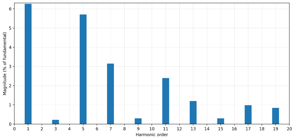
In measurements, resonance often appears as a harmonic spectrum, with one harmonic voltage much higher than expected. A typical VFD spectrum may contain several harmonic orders, but a resonant installation often shows one or two dominant voltage harmonics.
| Measurement | Interpretation |
|---|---|
| One harmonic voltage dominates the spectrum. | The network may have high impedance at that harmonic order. |
| Total Harmonic Voltage Distortion (THDu) changes strongly with VFD load. | The resonance point is changing with the operating condition. |
| Voltage distortion is high, but current distortion is not equally high. | The network is amplifying the voltage response. |
The important measurement is not only the Total Harmonic Voltage Distortion (THDu). THDu gives the total distortion level, but it does not show why the distortion is high. The individual harmonic spectrum is needed to determine whether a resonance-related harmonic is dominant.
Resonance damping vs. conventional active harmonic filtering
A key difference between Merus® Resonance Damping and conventional harmonic current compensation is that resonance damping addresses the resonant network condition itself, not only the harmonic current that excites it.
Resonance damping should not be treated as equivalent to conventional harmonic current compensation, resonance suppression, or resonance avoidance. Those approaches may reduce the harmonic current at the resonance frequency, but they do not eliminate the resonance condition itself and may even increase voltage distortion.
Therefore, conventional methods may reduce current harmonics but will leave the network voltage distortion at a level that is not acceptable by power quality standards. Resonance damping acts on the resonance condition itself by reducing the network response at the resonant harmonic order, which is required when voltage distortion must be brought to an acceptable power-quality level.
| Topic | Conventional current-compensation Active Harmonic Filter | Merus® Resonance Damping |
|---|---|---|
| Primary target | Load harmonic current | Resonant voltage response and harmonic current |
| Control principle | Inject opposite harmonic current to reduce upstream current distortion | Inject damping current based on selected harmonic voltage components |
| Effect on resonance peak | Does not directly damp the impedance peak and increases the voltage distortion | Actively dampens the resonant response at selected harmonic orders |
| Best fit | Non-resonant or well-damped installations where current harmonics are the main issue | VFD installations where low harmonic voltage distortion is required |
Different harmonic detection methods
Conventional AHF solutions based mainly on Discrete Fourier Transform (DFT) harmonic detection and current cancellation are not sufficient by themselves to eliminate or damp a harmonic resonance condition. A DFT-based approach introduces calculation delay, depends on waveform assumptions, and can be vulnerable in VFD installations with grid resonance, frequency variation, and incomplete sequence information.
Merus Power uses an advanced Individual Harmonics Synchronous Reference Frame (IH-SRF) detection method, required for the resonance damping feature, in which individual harmonics are handled in rotating reference frames synchronized with the mains voltage harmonics. This enables faster harmonic control, positive- and negative-sequence compensation, and harmonic-specific resonance damping, allowing the AHF to compensate for voltage distortion while also eliminating the resonance condition itself.
DFT-based harmonic detection is well-suited to measuring and analyzing harmonic content but less suitable for fast real-time control in VFD installations, as it requires waveform-window calculation and introduces control delay. Merus® solutions use the IH-SRF method where individual harmonics can be dynamically detected and controlled in synchronized rotating reference frames, enabling faster harmonic compensation and resonance damping under changing VFD load conditions.
| Parameters | FFT/DFT-based method | IH-SRF-based method |
|---|---|---|
| Estimation accuracy of harmonics | + + + High for steady signals | + + + High for all signals |
| Delay in estimation of harmonics | + – – Limited through analysis window | + + + Continuous tracking |
| Ability to adjust the response time | + – – Limited | + + + High and selectable for each harmonic |
| Robustness to network resonances | + – – Limited | + + + High |
| Handling unbalance of harmonics | – – – Limited | + + + Tracks sequences individually |
| Robustness to frequency variations | + – – Sensitive | + + + Follow real grid frequency |
Real-world VFD installation: measured resonance damping results
This section presents results from a real customer installation in which harmonic resonance was identified through site measurements, and resonance damping was implemented and measured under actual operating conditions.
Site measurements before resonance damping
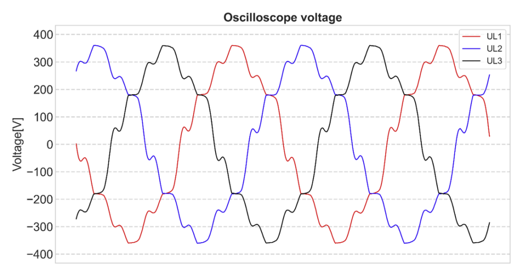
Initial power quality measurements showed very high harmonic voltage distortion, with approximately 12% THDu, while the target was to reduce THDu below 5%. The voltage harmonic limits were evaluated against the G5/5 power quality standard.
Site measurements indicate that the installation is experiencing harmonic resonance, meaning the network is amplifying certain harmonic voltages rather than only exhibiting normal VFD harmonic emissions.
Because of this resonance, conventional mitigation methods are not sufficient to reduce the harmonic voltage distortion to the required level. The site contains a very large number of VFDs, making installation of an AC-reactor on each drive not a viable solution. Drives are used on compressors, vacuum pumps, and filtration systems.
| Voltage (V) | THDu [%] |
|---|---|
| 235,31 | 11,69 % |
| Harmonic | V | [%] | Limit [%] | Fulfill |
|---|---|---|---|---|
| 3 | 0,23 | 0,1 | 4,00 | ✅ |
| 5 | 18,39 | 7,83 | 4,00 | ❌ |
| 7 | 7,79 | 3,32 | 4,00 | ✅ |
| 9 | 1,13 | 0,48 | 1,20 | ✅ |
| 11 | 14,35 | 6,11 | 3,00 | ❌ |
| 13 | 11,4 | 4,86 | 2,50 | ❌ |
| 15 | 1,02 | 0,43 | 0,50 | ✅ |
| 17 | 4,15 | 1,77 | 1,60 | ❌ |
| 19 | 1,38 | 0,59 | 1,50 | ✅ |
| 21 | 0,07 | 0,03 | 0,20 | ✅ |
| 23 | 0,55 | 0,23 | 1,20 | ✅ |
| 25 | 0,53 | 0,22 | 1,00 | ✅ |
| Harmonic | V | [%] | Limit [%] | Fulfill |
|---|---|---|---|---|
| 2 | 0,37 | 0,26 | 1,60 | ✅ |
| 4 | 0,24 | 0,12 | 1,00 | ✅ |
| 6 | 0,04 | 0,12 | 0,50 | ✅ |
| 8 | 0,14 | 0,06 | 0,40 | ✅ |
| 10 | 0,25 | 0,14 | 0,40 | ✅ |
| 12 | 0,23 | 0,06 | 0,20 | ✅ |
| 14 | 0,28 | 0,18 | 0,20 | ✅ |
| 16 | 0,19 | 0,09 | 0,20 | ✅ |
| 18 | 0,04 | 0,08 | 0,20 | ✅ |
| 20 | 0,07 | 0,07 | 0,20 | ✅ |
| 22 | 0,02 | 0,04 | 0,20 | ✅ |
| 24 | 0,04 | 0,04 | 0,20 | ✅ |
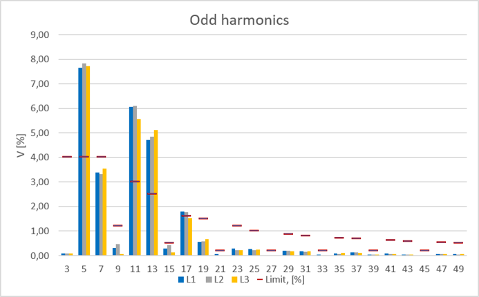
The measured waveform and harmonic spectrum differed significantly from a typical VFD harmonic spectrum. The measurements showed that resonance was particularly affecting the 11th and 13th harmonics.
Measured effect of resonance damping
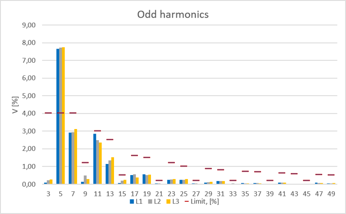
Resonance damping was then applied to the installation and the resulting harmonic voltage spectrum was measured.
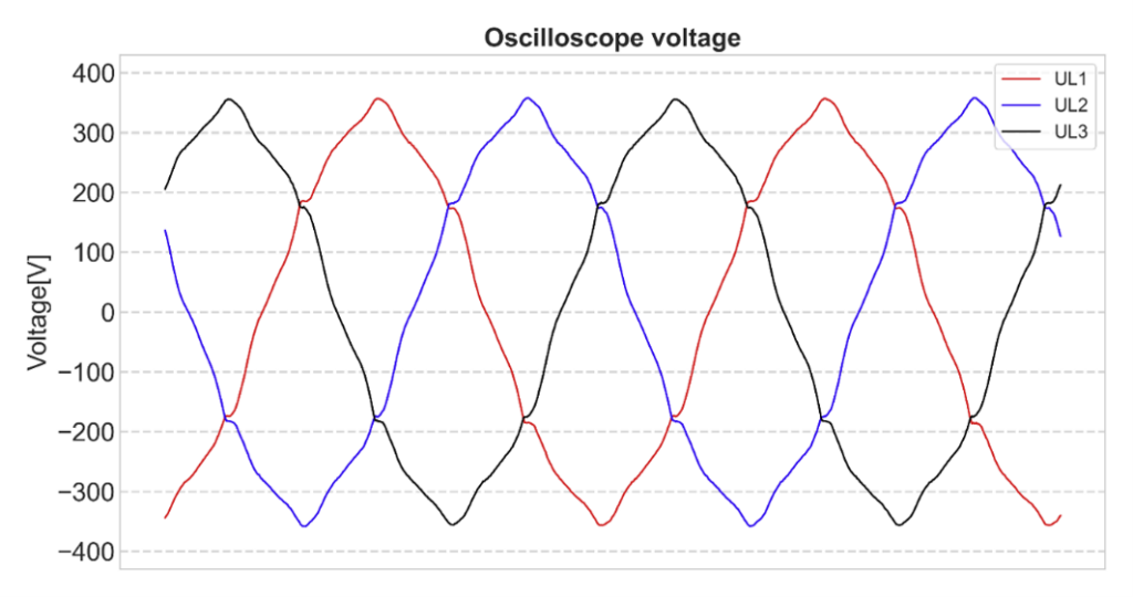
With resonance damping active, the measured voltage harmonic spectrum now resembles a typical VFD installation. This demonstrated that the resonance damping eliminates the resonance condition on the 11th and 13th harmonics.
Full harmonic compensation after resonance damping
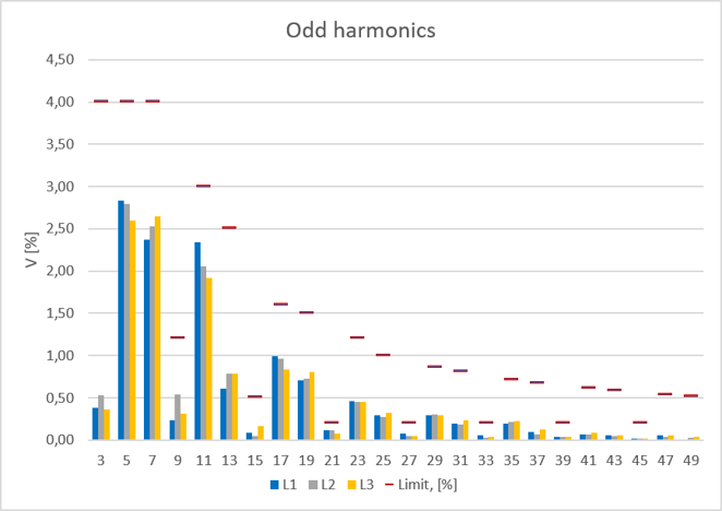
Once the resonance condition had been sufficiently damped, current-based harmonic compensation could be applied without exciting the problematic harmonic voltages. This allowed the remaining harmonic distortion to be reduced to the required level.
| Voltage (V) | THDu [%] |
|---|---|
| 235,75 | 4,52 % |
| Harmonic | V | [%] | Limit [%] | Fulfill |
|---|---|---|---|---|
| 3 | 0,86 | 0,18 | 4,00 | ✅ |
| 5 | 6,17 | 2,81 | 4,00 | ✅ |
| 7 | 6,29 | 2,37 | 4,00 | ✅ |
| 9 | 0,75 | 0,14 | 1,20 | ✅ |
| 11 | 4,54 | 2,31 | 3,00 | ✅ |
| 13 | 1,87 | 0,58 | 2,50 | ✅ |
| 15 | 0,40 | 0,08 | 0,50 | ✅ |
| 17 | 1,99 | 0,91 | 1,60 | ✅ |
| 19 | 1,92 | 0,60 | 1,50 | ✅ |
| 21 | 0,17 | 0,11 | 0,20 | ✅ |
| 23 | 1,06 | 0,35 | 1,20 | ✅ |
| 25 | 0,77 | 0,21 | 1,00 | ✅ |
| Harmonic | V | [%] | Limit [%] | Fulfill |
|---|---|---|---|---|
| 2 | 0,71 | 0,22 | 1,60 | ✅ |
| 4 | 0,13 | 0,11 | 1,00 | ✅ |
| 6 | 0,25 | 0,05 | 0,50 | ✅ |
| 8 | 0,22 | 0,08 | 0,40 | ✅ |
| 10 | 0,19 | 0,07 | 0,40 | ✅ |
| 12 | 0,45 | 0,03 | 0,20 | ✅ |
| 14 | 0,07 | 0,02 | 0,20 | ✅ |
| 16 | 0,03 | 0,03 | 0,20 | ✅ |
| 18 | 0,23 | 0,03 | 0,20 | ✅ |
| 20 | 0,08 | 0,03 | 0,20 | ✅ |
| 22 | 0,04 | 0,02 | 0,20 | ✅ |
| 24 | 0,09 | 0,01 | 0,20 | ✅ |
Resonance damping with Merus Power’s active filters
The Merus® A2 Active Harmonic Filter provides dynamic power quality compensation for electrical networks with VFDs and other non-linear loads. In addition to conventional harmonic current compensation, Merus® technology can provide harmonic-specific resonance damping when network resonance is causing excessive harmonic voltage distortion.
This allows the same active filtering solution to address two different power quality challenges: reducing harmonic currents generated by non-linear loads and damping problematic network resonances that amplify harmonic voltage distortion.
Merus Power combines active harmonic filtering technology with power quality engineering expertise, allowing resonance-related problems to be evaluated based on the behavior of the electrical network rather than harmonic current levels alone.

Merus® A2 – Active Harmonic Filter
Merus® A2 is a scalable, versatile, and durable active harmonic filtering solution designed and manufactured in Finland using innovative Merus® technology.
Summary: Why resonance damping matters in VFD installations
Harmonic resonance is a real power quality problem in VFD installations. It occurs when the installation impedance amplifies harmonics, converting normal VFD harmonic currents into excessive harmonic voltage distortion at the PCC.
This makes the distortion level dependent on grid impedance, the operating VFD population, and the loading condition. As a result, a site can operate acceptably under one condition and exceed harmonic voltage limits under another.
The real-world measurements presented in this article demonstrate this behavior. Before compensation, the installation had approximately 12% THDu, with several individual harmonic voltage limits exceeded. After resonance damping and harmonic compensation, THDu was reduced to 4.52%, and the measured individual harmonic voltages fulfilled the G5/5 limits.
The practical conclusion is that conventional harmonic current compensation alone is insufficient when network resonance remains active. The resonant response must first be damped so that harmonic current compensation can operate without further exciting harmonic voltages. Once the resonance is eliminated, normal harmonic current compensation is able to reduce the remaining voltage distortion to an acceptable level.
Anything on your mind? Let’s talk!