
Are all STATCOMs the same?
STATCOM stands for Static Synchronous Compensator and is part of the Flexible AC Transmission System (FACTS) family. In modern power grids, STATCOMs are widely used across a range of applications. They can be found in transmission and distribution networks, wind and solar farms, as well as in heavy industries such as steel plants. But are all STATCOMs the same?
In this article, we explore the key differences between two common STATCOM technologies: the 3-level and the multilevel topologies. The 3-level topology uses three voltage levels, whereas the multilevel topology consists of multiple series-connected levels, with the number of levels determined by the connection voltage. It is worth noting that these terms are not strictly defined in academic literature. However, they serve as practical ways to distinguish between these two technologies.
Two main STATCOM technologies
The 3-level topology is widely used across a range of power electronics applications, including STATCOMs, AHFs (Active Harmonic Filters), and wind turbines. The name refers to the three voltage levels used in its power electronics: positive, zero, and negative.
Multilevel topology, as the name suggests, operates with a higher number of voltage levels. This technology is commonly used in STATCOMs as well as in High-Voltage Direct Current (HVDC) applications.
Both technologies include several design variations. However, in this article, we focus on the key differences that arise from their fundamentally different architectures.
How STATCOMs connect to the medium voltage grid
One of the most fundamental differences between these technologies lies in how their power electronics are connected to the grid.
In 3-level systems, the inverter modules operate at a lower voltage than the medium voltage grid. As a result, one or more transformers are required to step the voltage down to a suitable level for the modules.
Because power semiconductors are not directly connected to the AC bus, 3-level inverters typically include LCL filters to mitigate switching-frequency currents.
Multilevel STATCOMs, in contrast, connect directly to the medium voltage grid. A reactor is placed between the power electronics and the grid, forming an L filter. In some cases, a high-pass filter may also be connected to the medium-voltage bus to prevent switching-frequency currents from propagating into the wider grid.

What this means for system behavior
These different connection approaches have important implications, particularly when it comes to fault levels and system behavior.
In 3-level systems, the main impedances affecting the fault level at the inverter terminals are the transformer and the supplying grid. The STATCOM current and short-circuit currents on the transformer’s low-voltage side set practical upper limits for how many modules can be connected to a single low-voltage bus.
In larger systems with multiple transformer groups, increasing total power typically means adding more transformers rather than increasing the size of existing ones. As a result, transformer impedance remains relatively constant as the system scales.
Since transformer impedance is typically much higher than grid impedance, the STATCOM modules experience relatively stable fault level conditions, regardless of variations in grid strength or system size.
In multilevel STATCOMs, the situation is different. The size of the output reactor scales with the system capacity. This means the relative shares of grid and reactor impedance vary with both the grid fault level and the STATCOM size. As a result, the fault level seen by the inverter terminals is not constant.
Example: impact of system size
Consider two STATCOM systems rated at 25 MVAr and 100 MVAr, both connected to a 33 kV grid with a fault level of 1000 MVA.
For a 3-level solution, assuming a maximum transformer size of 25 MVA with 5% impedance, the smaller system uses 1 transformer, while the larger system uses 4. Despite this, the relative impedance seen by the power modules remains the same in both cases: approximately 33% from the grid and 67% from the transformer.
For a multilevel STATCOM, the proportions vary with system size. In the 25 MVAr case, the impedance is roughly 8% from the grid and 92% from the reactor. In the 100 MVAr system, these values shift to about 25% grid and 75% reactor.
Another way to view this is through the ratio between the power electronics’ nominal output power and the fault level. In 3-level systems, this ratio remains constant as the system scales. In multilevel systems, the ratio decreases as the STATCOM size increases.
This has practical implications. For example, control system dynamics are often influenced by the relationship between nominal power and fault level at the connection point.
Modularity and scalability
How modular are these technologies?
In a 3-level topology, each inverter is an independent three-phase unit. The rated capacity of an inverter, therefore, defines the smallest increment in STATCOM capacity. Typically, these modules handle lower voltages and currents than their multilevel counterparts, allowing for finer granularity in system sizing.
This makes it easier to match the STATCOM capacity precisely to the application requirements, without significant over- or under-dimensioning.
Another advantage is that transformers between the modules and the medium-voltage bus can be oversized during the initial design phase, allowing for future expansion.
In multilevel systems, the situation is different. These systems use a valve-type construction, where the size of a single valve defines the modularity. Because these valves operate at higher voltages, their power output is typically much larger. As a result, each valve represents a significant portion of the total system capacity, and in some cases, there is only one valve per phase.
For this reason, it is often more difficult to fine-tune the capacity of a multilevel STATCOM to match exact requirements. In addition, because each valve requires its own coupling reactor, expanding the system later is less straightforward than in 3-level solutions.
Reliability considerations
Reliability is handled differently in the two technologies.
In multilevel valve-type designs, redundancy is typically achieved by adding extra series-connected levels. Each level shares a portion of the medium voltage.
If one level fails, it is usually bypassed. This increases the voltage stress on the remaining levels. If this stress exceeds the semiconductor limits, the entire valve must be disconnected. Since valves are single-phase units, this leads to a trip of the entire STATCOM.
The number of redundant levels is a trade-off between cost and reliability, with typical designs including one or two redundant levels.
In 3-level systems, the modules operate in parallel. If one module fails, the remaining modules continue operating at the same voltage. The overall capacity is simply reduced in proportion to the lost module. In theory, the system could continue operating with only a single healthy module, although this would have limited practical value.


Another important aspect is maintainability. In 3-level systems, independent modules and transformer groups can be isolated, allowing repairs while the rest of the system remains in operation.
In multilevel systems, this is more challenging. Enabling repairs without a shutdown would require hot-swappable modules connected directly to medium-voltage systems, which would likely be classified as live work. Whether such solutions are used in practice depends on the specific implementation.
Footprint considerations
Footprint is another area where the technologies differ.
Multilevel STATCOMs use valve-type inverters, typically one per phase. While the size of valves and their coupling reactors varies, their footprint does not increase significantly with system capacity.
In contrast, 3-level systems are based on individual modules. As system capacity increases, so does the number of modules and, consequently, the overall footprint.
For smaller systems, 3-level solutions can have a more compact footprint. However, in larger installations, multilevel technology often offers greater space efficiency.
Conclusion
What can we conclude from these differences?
As is often the case in engineering, there is no single optimal solution for every situation. Each technology comes with its own strengths and trade-offs, and its relevance depends on the specific application.
The key question is not only what the STATCOM should do, but also under what conditions it will operate. Whether the goal is flicker mitigation, harmonic compensation, or voltage control in a transmission network, the underlying system characteristics are crucial.
For this reason, selecting a STATCOM solution should not be based solely on individual specifications. A more effective approach is to evaluate the application holistically, considering both the technical requirements and the operating environment.
At Merus Power, our STATCOM solutions are built on a modular architecture that enables flexible sizing, high reliability, and adaptability across different operating environments. By combining dynamic reactive power compensation, voltage stabilization, and harmonic filtering into a single solution, Merus® STATCOM systems are designed to address the diverse power-quality challenges encountered in modern grids and industrial processes.
Because every application is different, we work closely with our customers throughout the design and implementation process to ensure that the solution matches their operational requirements, technical constraints, and long-term goals. This collaborative approach helps ensure that each STATCOM system delivers the intended performance and value throughout its lifecycle.
Get to know our solution!
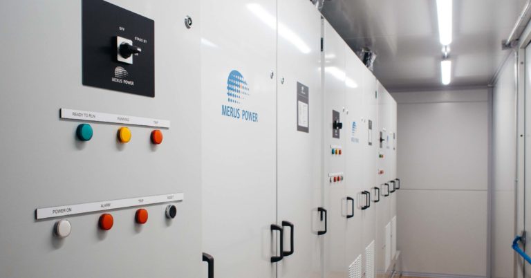
Merus® STATCOM – Static Synchronous Compensator
Merus® STATCOM is a modular and modern Static Synchronous Compensator for demanding applications and heavy industrial loads.
Anything on your mind? Let’s talk!


Lasse Hietikko
Sales Manager, Power Quality,
Hydrogen & Renewables