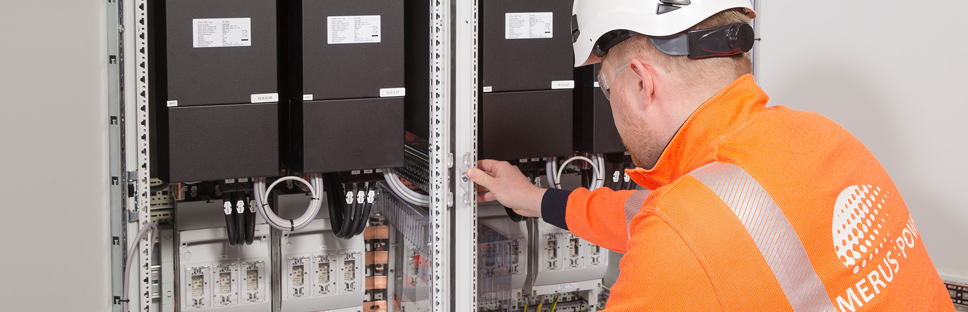
From traditional capacitor banks to hybrid power quality
Power Factor Correction (PFC) has evolved from simple capacitor banks to comprehensive Power Quality (PQ) solutions as electrical networks have become increasingly complex. Traditional capacitor banks remain an effective means of compensating for reactive power and improving the power factor. However, in modern networks with significant levels of harmonics generated by non-linear loads, capacitor banks can contribute to resonance conditions and increase operational risk.
The evolution of Power Factor Correction in modern electrical networks
To address these challenges, Detuned PFC systems use series reactors to reduce the risk of harmonic resonance, while Active Harmonic Filters (AHFs) provide dynamic reactive power compensation together with harmonic mitigation and load balancing. Hybrid Power Quality (HPQ) solutions combine passive and active technologies in a coordinated system, offering a broader approach to power quality management. As a result, selecting a compensation solution is no longer based solely on reactive power demand (kVAr) but on the overall power-quality requirements of the installation.
Electrical networks have changed significantly over the past decades. Historically, low-voltage systems were dominated by motors, transformers, and other linear loads. Under these conditions, power factor correction was relatively straightforward: capacitor banks were installed to compensate inductive reactive power, reduce current flow, minimize losses, and improve power factor.
Today, industrial and commercial networks contain large numbers of variable frequency drives (VFDs), rectifiers, power electronic converters, switch-mode power supplies, LED lighting systems, welding equipment, renewable energy converters, and other non-linear loads. While these technologies improve efficiency, controllability, and energy performance, they also introduce new power quality challenges, including harmonic distortion, voltage distortion, rapidly changing reactive power demand, phase unbalance, and resonance phenomena.
Consequently, determining the optimal compensation strategy requires more than a simple kVAr calculation. Engineers must evaluate the complete power quality environment, including harmonic levels, network impedance characteristics, load dynamics, compliance requirements, and future expansion plans.
This evolution has led to the progressive development of compensation technologies:
Traditional PFC → Tuned and Detuned PFC → Active Harmonic Filters (AHF) and Static VAR Generators (SVG) → Hybrid Power Quality (HPQ) Systems
Understanding the capabilities, advantages, and limitations of each stage is essential for selecting the most effective solution for modern electrical networks.
Basic Theory: P, Q, S and Power Factor
To understand power factor correction and power quality solutions, three fundamental power quantities must first be understood.
Active Power (P)
- Active power is converted into useful work such as mechanical output, heat, lighting, or industrial processes.
- Unit: W, kW, MW
Reactive Power (Q)
- Reactive power is required to establish magnetic and electric fields. Motors, transformers, and reactors consume inductive reactive power, while capacitors generate capacitive reactive power.
- Unit: var, kvar, MVAr
Apparent Power (S)
- Apparent power represents the total electrical loading of the system. Transformers, cables, switchgear, and protective devices must be sized according to apparent power.
- Unit: VA, kVA, MVA
In a sinusoidal system:
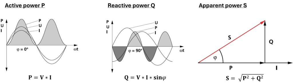
A low power factor means that more current is needed to transmit the same useful active power. This increases losses, voltage drops, and the loading of transformers, cables, and switchgear. Proper power factor correction reduces unnecessary reactive current and improves the usable capacity of the electrical network.
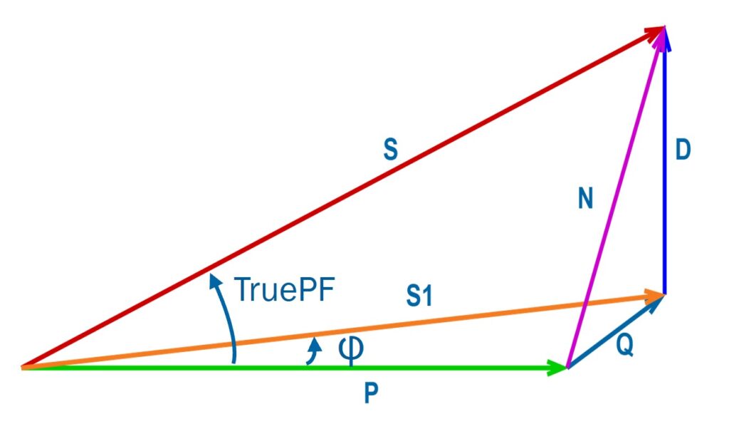
It is also important to distinguish between:
cos φ
- Represents the phase displacement between voltage and current at the fundamental frequency (50/60 Hz).
True Power Factor (True PF)
- Includes both displacement power factor and harmonic distortion effects.
Traditional PFC: Capacitor banks without reactors
Power factor correction was achieved using capacitor banks without reactors for decades. This was a logical and cost-effective solution in networks with low harmonic distortion.
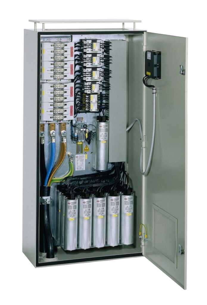
However, a capacitor bank without reactors forms a resonance circuit together with the network inductance, mainly the transformer impedance and cable impedance. This can create serious problems when harmonics are present.
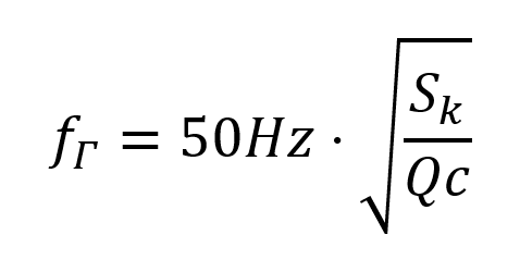
For the resonance frequency “fr“, a simple calculation formula (50 Hz network):
where
Sk = short-circuit power at the connection point of the capacitor
Qc = the reactive power of the capacitor
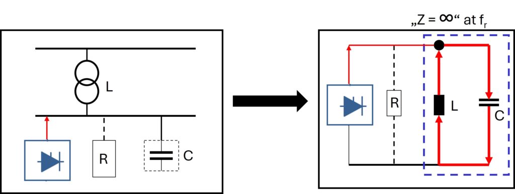
Parallel resonance
In parallel resonance, the network inductance and the capacitor bank form a resonance circuit where the impedance becomes very high at a resonance frequency. Even a small harmonic current from a nonlinear load at the network resonance frequency can cause:
- Voltage distortion amplification
- Capacitor overload
- Increased harmonic voltage levels
- Equipment overheating
- Protection malfunctions
Series resonance
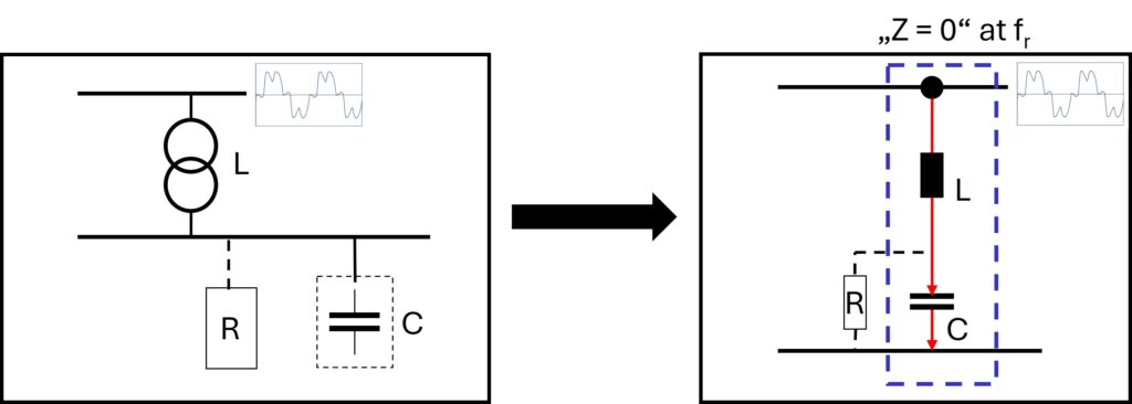
In series resonance, the impedance becomes very low at the resonance frequency. This can draw harmonic currents from upstream networks and significantly increase current stress on capacitors and other system components at a lower voltage level.
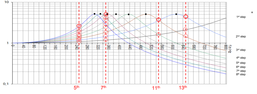
The resonance frequency of a capacitor bank is not constant, and changes with the number of capacitor steps energized. Consequently, resonance conditions may occur near characteristic harmonic frequencies present in the network, resulting in increased harmonic distortion and amplification of harmonic currents, particularly at the:
- 5th harmonic
- 7th harmonic
- 11th harmonic
- 13th harmonic
Detuned PFC: The safer passive solution
Over the last two to three decades, as harmonic distortion levels in electrical networks have increased, detuned power factor correction has become the preferred solution for reactive power compensation.
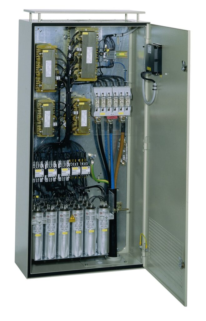
A detuned PFC system consists of capacitors connected in series with reactors.
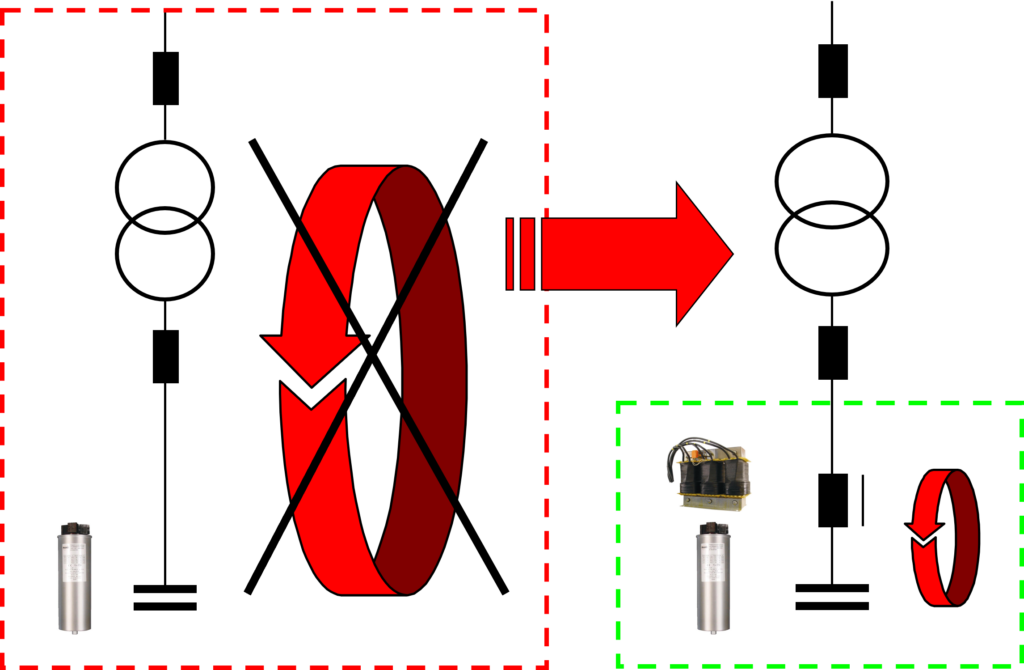
The series connection of a capacitor step and its detuning reactor shifts the system resonance frequency (fr) below the lowest dominant network harmonic, typically the 5th.
For example, a 50 Hz system:
- 5th harmonic = 250 Hz
- Typical detuning frequency: fr = 189 Hz
- Detuning factor: p = 7%
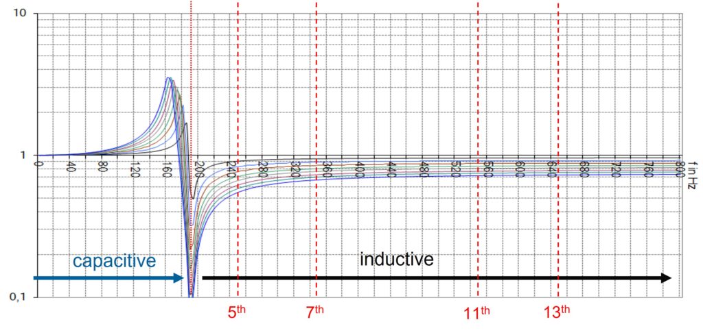
- Below the resonance frequency (fr), the detuned step behaves capacitively.
- Above the resonance frequency (fr), the detuned step behaves inductively.
- Therefore, at the 5th and higher harmonic frequencies, the detuned PFC system behaves inductively and significantly reduces the risk of resonance with the network inductance.
The suitable resonance frequency (fr) of a detuned PFC system is determined by the network harmonics and the required results. The following figure shows examples of commonly used detuned systems (50 Hz network):
| Detuning factor p [%] | Resonance frequency fr [Hz] |
|---|---|
| 5.67 % | 210 Hz |
| 6 % | 204 Hz |
| 7 % | 189 Hz |
| 8 % | 177 Hz |
| 12.5 % | 141 Hz |
| 14 % | 134 Hz |
Detuned PFCs have many benefits:
- Reduced resonance risk
- Improved capacitor protection
- Lower risk of absorbing utility harmonics
- Better network stability
- Low investment costs
Important engineering rule
Detuned and non-detuned capacitor banks should never be installed in the same low-voltage network. Such combinations can create new resonance conditions and amplify especially higher harmonics.
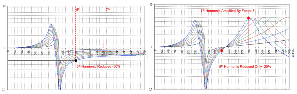
Right: Mix of detuned and non-detuned Capacitor Banks in the same network.
Detuned PFC compared with tuned Passive Harmonic Filters
Detuned PFC systems and tuned Passive Harmonic Filters are sometimes confused, although they serve different purposes.
A Detuned PFC system is designed to avoid harmonic resonance. Its resonance frequency (fr) is intentionally placed below the lowest relevant network harmonic (e.g., 189 Hz at a 50 Hz network).
A Tuned Passive Harmonic Filter is designed to absorb harmonic currents at specific harmonic frequencies. Typical tuning frequencies include: 5th, 7th, 11th, and 13th harmonics.
Because of this, the tuned steps must be sized large enough to handle all existing harmonic current in the network. This leads to poor reactive power regulation and creates a risk when network conditions change later due to new non-linear loads or increased harmonic levels in the upstream network.
With detuned PFC systems, smaller capacitor steps can be used. It makes the system better suited to varying reactive power demand. In addition, overcompensation under low-load conditions can be avoided, which is a common issue with tuned passive harmonic filters.
Why Active Harmonic Filters are becoming more common
Active Harmonic Filters (AHF) are becoming a standard solution in many industrial, infrastructure, and renewable energy networks.
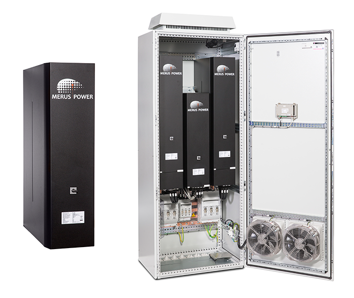
Modern electrical networks contain significantly more nonlinear loads than ever before. These loads exhibit a wide range of frequencies and varying amplitudes due to changing operating conditions, while their characteristic frequencies may also change over time. In addition, the increasing penetration of power-electronic-based renewable generation, such as solar and wind power, weakens the grid and causes the network’s resonance frequencies to shift. Consequently, a tuned passive filter, such as the one described above, for a single target frequency may not provide adequate long-term performance.
Examples of non-linear loads:
- Variable Frequency Drives (VFD)
- UPS systems
- Data centers
- Solar inverters
- EV chargers
- Welding equipment
- LED lighting systems
These non-linear devices generate harmonic currents that increase:
- Transformer losses
- Cable losses
- Equipment heating
- Voltage distortion
- Neutral currents
- Risk of resonance
- Overloading of capacitors
- Protective device tripping
- EMI/EMC interference levels
At the same time, power quality standards and grid code requirements have become increasingly important. Examples include:
- IEEE 519
- IEC 61000 series
- EN 50160
- Engineering Recommendation G5/5
As a result, harmonic mitigation has become a much more fundamental aspect of modern power quality engineering. In parallel, active filter technology has evolved significantly, offering improved performance, faster response times, and broader compensation capabilities, while overall system costs have decreased due to technological advancements and wider adoption.
This combination of increasing harmonic challenges and improved mitigation technologies has accelerated the shift toward integrated power quality solutions, in which reactive power compensation and harmonic filtering are addressed within a unified system approach.
How an Active Harmonic Filter works
An Active Harmonic Filter (AHF) is connected in parallel with the nonlinear load or at the point of common coupling (PCC). The AHF continuously measures current waveforms, identifies harmonic components, and injects equal currents in opposite phase.
This results in the cancellation of harmonic currents before they spread to other parts of the network or reach the upstream system.
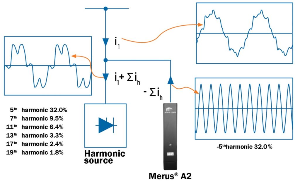
An Active Harmonic Filter operates as a controllable current source.
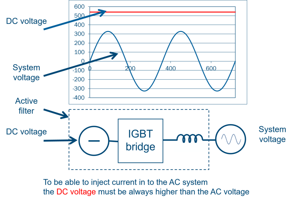
Modern Merus® A2-Active Harmonic Filters provide multiple power quality functions simultaneously, including:
- Harmonic compensation using advanced control algorithms (both DFT and SFR methods), supported by a highly accurate PLL
- Dynamic, stepless reactive power compensation (inductive and capacitive)
- Phase current correction (load balancing)
- Resonance damping to improve network stability
- Neutral current compensation
Because compensation is generated electronically, performance automatically adapts to changing load conditions.
Passive tuned filters are typically applied only in stable industrial environments, while active harmonic filters (AHFs) have become the dominant solution for modern non-linear and variable loads, progressively replacing traditional tuned passive filter systems across a wide range of applications.
Tuned Passive Filter vs. Active Harmonic Filter comparison
| Parameter | Passive Harmonic Filters | Active Harmonic Filters |
|---|---|---|
| Harmonic Range | Selected orders (e.g. 5th, 7th, 11th, 13th) | Multiple harmonic orders (up to the 50th) |
| Adaptability | Fixed compensation characteristics | Dynamic, stepless, and fast adaptation |
| Resonance Risk | Possible due to network resonance interactions | Low (Merus® A2 includes active resonance damping) |
| Reactive Power Compensation | Fixed (risk of overcompensation during low-load conditions) | Dynamic, fast and stepless (inductive and capacitive) |
| Response Time | Slow | Milliseconds |
| Suitable Application | Stable and predictable loads | Dynamic and rapidly changing loads |
Static Var Generators: Dynamic reactive power compensation
Some networks require just dynamic VAR control, without significant harmonic mitigation and load balancing. This has led to the use of Static VAR Generators (SVG).
Unlike Active Harmonic Filters, SVG systems are optimized primarily for reactive power compensation rather than harmonic mitigation (i.e., “downgraded AHF”).
Like AHF, SVG is a converter-based compensator that operates as a controllable reactive current source.
Unlike capacitor banks, SVG systems provide:
- Continuous compensation
- Stepless control
- Fast response
- Bidirectional reactive power flow
Benefits include:
- Response times below one cycle
- Improved voltage stability
- Elimination of capacitor switching transients
- High performance under rapidly changing load
However, despite their advantages in dynamic reactive power compensation, SVGs also have several disadvantages compared with detuned capacitor banks. Many commercially available low-cost SVGs are primarily designed to rapidly compensate fundamental-frequency reactive power and are not specifically optimized for harmonic mitigation. Consequently, they may not provide sufficient harmonic filtering and, depending on network characteristics and control strategy, may even contribute to increased harmonic distortion.
Another important disadvantage of SVGs is their lower energy efficiency compared with passive compensation solutions such as detuned capacitor banks. Due to semiconductor switching losses and auxiliary power consumption, SVGs require continuous active power during operation. These additional losses, typically amounting to several percent compared with capacitor-based solutions, can significantly increase operating expenditure (OPEX), particularly in high-power installations with continuous operation. Furthermore, the associated heat generation increases thermal management requirements and may require additional cooling capacity, further reducing overall system efficiency.
Hybrid power quality: The next step
The latest development in power quality technology is the Merus® Hybrid Power Quality (HPQ) system.
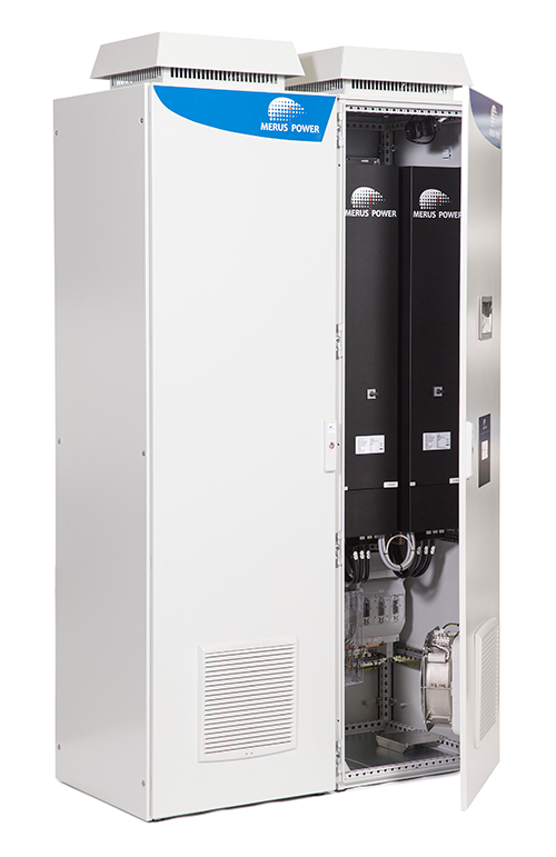
A Merus® HPQ system combines:
- Detuned capacitor banks
- Active Harmonic Filters (A2-HPQ)
- Common intelligent control
The Active Harmonic Filter provides:
- Dynamic harmonic compensation
- Fast and stepless reactive power compensation (inductive and capacitive)
- Load balancing
- Neutral current reduction
The detuned capacitor bank provides the majority of the required fundamental-frequency reactive power with very high efficiency and low operating cost. By combining passive compensation with the advanced power-quality capabilities of an active harmonic filter (A2-HPQ), the solution leverages the efficiency advantages of passive technology while adding active compensation functions, including fast, stepless reactive power control, harmonic mitigation, and phase balancing.
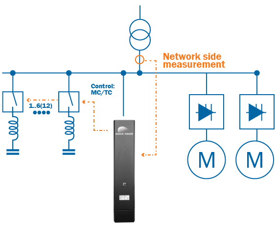
What is a real hybrid system?
A real HPQ system is not simply an Active Harmonic Filter (AHF) and a detuned capacitor bank or static var generator (SVG) installed together.
If these two systems operate independently, they just remain two separate systems.
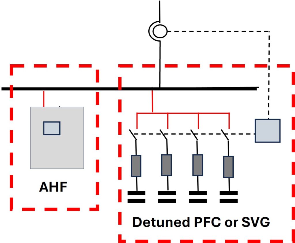
In a real Merus® HPQ system, one common controller coordinates both technologies.
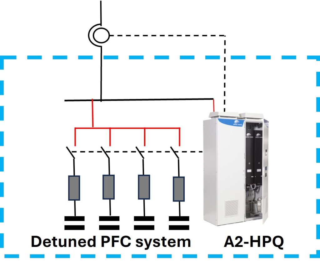
The common controller determines:
- Capacitor switching sequence
- Dynamic compensation requirements
- Harmonic mitigation strategy
- Load balancing requirements
This coordinated approach maximizes performance and minimizes interaction between active and passive components. It also significantly simplifies the integration of instrument transformers for measurement. Thanks to its integrated control, the HPQ system can be connected to a single switchboard feeder while effectively managing the required power quality functions.
Summary: The evolution of power quality solutions
Electrical networks have evolved dramatically over the past decades.
Traditional capacitor banks (PFC) were sufficient when networks contained mainly linear loads.
As harmonics increased, detuned PFC systems became necessary to reduce resonance risks and improve reliability.
Where significant harmonic mitigation was required, Tuned Passive Harmonic Filters provided targeted compensation for selected harmonic frequencies.
As networks became more dynamic and harmonic spectra less predictable, Active Harmonic Filters (AHFs) have emerged as the preferred solution for flexible and adaptive harmonic mitigation, reactive power compensation (inductive and capacitive), and load balancing.
Static Var Generators (SVGs) provide electronic reactive power compensation at a lower capital cost than active harmonic filters (AHFs), but do not deliver the full functionality of AHF systems.
Today, HPQ systems combine the strengths of passive and active technologies under a common control platform.
Numerous detuned PFC systems are currently installed and operating at customer sites. Merus® A2-HPQ modules offer a simple and cost-effective retrofit solution that upgrades these existing detuned PFC systems with Active Harmonic Filter capabilities to meet evolving network and grid code requirements, thereby eliminating the need to replace the entire detuned PFC system with a new Active Harmonic Filter or SVG.
Comparison of main solution types
| Solution | Benefits | Disadvantages | Best fit |
|---|---|---|---|
| Traditional PFC without reactors | Simple, low investment cost, suitable only for networks with very low harmonic levels and limited reactive power compensation needs. | High resonance risk, capacitor overload risk, and poor harmonic compatibility. | Systems with stable operating conditions, minimal harmonic distortion, and low reactive power compensation requirements → rarely used today. |
| Detuned PFC | Avoids dangerous resonance and protects capacitors. Robust design with smaller step sizes for improved control flexibility. Long service lifetime. Low CAPEX and OPEX. | Reduces lower-order harmonics slightly, or not at all, depending on the selected fr and Sk/Qc ratio. | Industrial networks with moderate harmonics and fundamental reactive power demand. |
| Tuned Passive Filter | Can filter selected harmonics effectively. | Requires a stable load profile, proper switching sequence, and careful engineering design. Risk of overcompensation under low-load conditions. Subsequent modifications or system expansions can be costly. | Large stable harmonic sources. |
| Static Var Generator (SVG) | Compensates dynamic reactive power (inductive and capacitive) and slightly lower-order harmonics. | “Downgraded AHF”, reduces only slightly low-order harmonics. | Networks, where dynamic reactive power compensation is needed. |
| Merus® Active Harmonic Filter (A2-AHF) | Provides dynamic compensation of harmonics, reactive power (inductive and capacitive), and unbalance. Modern A2-AHFs also include advanced resonance-damping functions and allow selection of harmonic-control algorithms, such as Discrete Fourier Transform (DFT) or Synchronous Reference Frame (SRF) methods. Easily expandable by adding additional Active Harmonic Filter (A2) modules. | Higher investment than passive PFC and requires correct dimensioning. | Modern networks with many nonlinear and variable loads. The SRF compensation technique is especially designed for networks where the load consists mainly of variable-speed drives. |
| Merus® Hybrid Power Quality (A2-HPQ) | Combines the benefits of detuned PFC and Active Harmonic Filter technologies within a single control platform. Enables cost-effective upgrading of existing detuned PFC systems with Active Harmonic Filter functionality, minimizing investment costs. Ensures low power losses for improved energy efficiency. Low CAPEX and OPEX. | More complex than a simple detuned PFC system and requires proper system engineering. | Sites with fundamental reactive power demand, harmonic distortion, and dynamic loads. Retrofit projects, where existing detuned PFC systems are upgraded with Active Harmonic Filter functionality. |
Power factor correction is no longer only about kVAr compensation. It is now an integral part of comprehensive Power Quality management. The future is hybrid: passive where it is most efficient, active where it is most effective, and intelligent control that enables both technologies to work together.
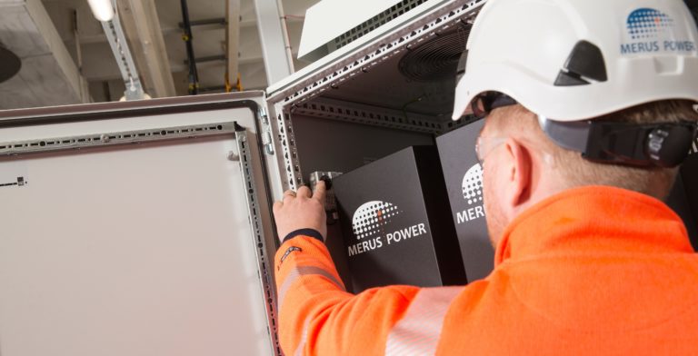
Merus® A2 – Active Harmonic Filter
Merus® A2 is a scalable, versatile, and durable active harmonic filtering solution designed and manufactured in Finland using innovative Merus® technology.
Merus® HPQ – Hybrid Power Quality
Merus® HPQ is an all-in-one power quality system for combined active harmonic mitigation and power factor correction.
Anything on your mind? Let’s talk!

Juhani Jaatinen
Senior Sales Manager,
DACH, Benelux, France, APAC